Machining PTFE rods requires a distinct approach compared to metals and harder plastics due to its soft, slippery, and thermally sensitive nature.
This article delves into common PTFE rod machining processes – turning, milling, and drilling, highlighting best practices, tooling considerations, and tips to achieve high-quality components.
Understanding PTFE’s Machinability
Before exploring specific machining methods, it’s essential to understand how PTFE behaves under cutting forces:
- Low Hardness and Elasticity: PTFE has a Shore D hardness around 50–60. Its softness and elasticity can lead to deflection under tool forces, making dimensional control challenging.
- Cold Flow Tendency: Under prolonged pressure, PTFE deforms (creeps). Clamping too hard or leaving parts under stress can cause dimension drift over time.
- Low Coefficient of Friction: While beneficial in final applications, this makes chip evacuation more difficult—chips tend to stick to tools or workpiece surfaces.
- Thermal Sensitivity: PTFE’s melting point is around 327 °C, but it begins to soften at lower temperatures (≈260 °C). Excessive heat can cause smearing, burn marks, or surface defects.
Successful PTFE rod machining hinges on selecting appropriate feeds, speeds, tooling, and workholding to minimize deflection, control heat, and ensure clean chip formation.
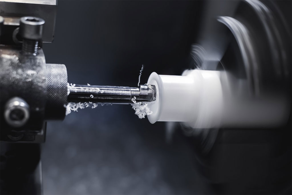
PTFE Rods Turning
1. Tooling Selection
- Cutter Material: Carbide or high-speed steel (HSS) with polished rake faces works well. Carbide tools hold edges longer but may be more prone to chipping if feed rates are too light. Polished HSS can prevent chip adhesion.
- Geometry: A positive rake angle (10°–15°) promotes shearing rather than plowing, reducing the tendency of PTFE to smear. A small nose radius (0.4 mm–0.8 mm) helps achieve fine finishes without excessive rubbing.
- Tool Coating: While PTFE generally does not adhere to uncoated tools, using TiN or DLC coatings can further reduce friction and improve chip evacuation.
2. Workholding and Stability
- Soft-Jaw Chucks: Because PTFE is soft, standard hard jaws can dig in, leading to distortion. Soft jaws (e.g., aluminum or brass inserts) conform to the rod and distribute clamping forces more evenly.
- Collets with Support: For smaller-diameter rods, collets with long contact surfaces minimize deflection. Ensuring the rod extends as little as possible beyond the chuck reduces vibration.
- Steady Rest: When turning long PTFE rods, a steady rest supports the workpiece near the cutting zone, reducing deflection and chatter.
3. Cutting Parameters
- Spindle Speed: Moderate speeds—typically 800–1,500 RPM for diameters between 10 mm and 50 mm—strike a balance between surface finish and heat generation. Higher speeds can cause heat build-up, leading to smearing.
- Feed Rate: A feed of 0.15–0.30 mm/rev produces a clean chip without excessive rubbing. Too slow a feed (below 0.1 mm/rev) yields long, stringy chips that entangle and smear; too fast (over 0.4 mm/rev) can overload the tool and increase deflection.
- Depth of Cut (DOC): Light DOC (0.5–2 mm) helps control heat. For roughing, depths up to 2 mm are feasible; finishing passes often use 0.2–0.5 mm to achieve fine surface finishes (<1 µm Ra).
4. Chip Control and Cooling
- Chip Breakers: Incorporating grooves or chip-breaker geometry on the tool can encourage short, curled chips that evacuate easily.
- Dry Machining Preferred: PTFE’s low thermal conductivity means that flood coolant may not effectively cool the cutting zone and can float chips, causing re-cutting. Ambient air is often sufficient. If coolant is necessary—for instance, when glass-filled PTFE generates more heat—a light mist of water-soluble oil is acceptable but must be minimal.
5. Common Turning Operations
- Facing: Produces a flat end face. Use light DOC (0.2–0.5 mm) and moderate feed to avoid smearing.
- Straight Turning: Reducing diameter along the length. Maintain consistent support to counter PTFE’s tendency to deflect; minimize overhang.
- Grooving/Parting: Use a carbide grooving insert with a sharp edge to cut a narrow slot. Cut slowly (feed ≈0.1 mm/rev) to prevent chip clogging. For parting off, ensure a sharp parting tool and minimal depth (≈1.5 mm per pass).
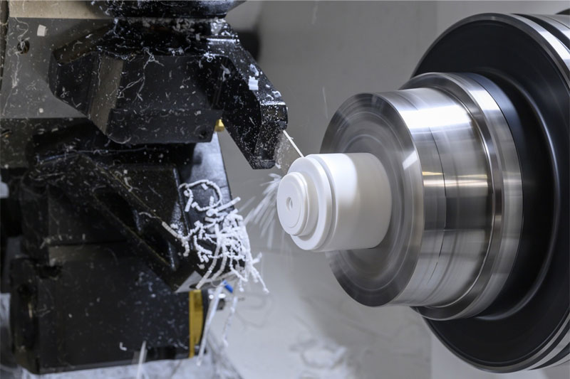
PTFE Rods Milling
Although PTFE machining often centers on turning, milling (especially CNC) enables complex features—slots, profiles, and holes. Milling PTFE rods, especially when mounted in fixtures, requires attention to tool geometry, workholding, and cutting conditions.
1. Tool Selection
- End Mills: Single-flute or two-flute end mills are preferred. A single flute with a polished surface produces larger chips and evacuates them more effectively, reducing heat build-up. Two-flute cutters are common but ensure polished flutes for chip release.
- Diameter: Tool diameter should be sufficiently small to maintain rigidity but large enough (e.g., 6 mm–12 mm) to avoid tool deflection.
- Coatings: Similar to turning, TiN or DLC coatings help reduce friction and prevent PTFE adhesion to the tool.
2. Fixture and Workholding
- Soft V-Blocks or Step Clamps: PTFE rods can be clamped in soft v-blocks lined with a thin layer of tape or rubber to prevent marring. Step clamps allow access for the tool to mill around the rod’s circumference.
- Vacuum Fixture: For smaller rods, a vacuum table can hold the rod in place without deformation—ideal when minimal contact is needed.
- Adhesive Fixturing: Double-sided tape or low-residue adhesive can temporarily bond PTFE rods to a fixture plate. Given PTFE’s low surface energy, ensure the adhesive is strong enough, or use a thin sacrificial backing.
3. Cutting Parameters
- Spindle Speed: 2,000–3,000 RPM is typical when using a 6 mm–12 mm end mill. Higher speeds risk heat accumulation; lower speeds can lead to poor surface finish.
- Feed Rate: For single-flute end mills, 0.05–0.15 mm/tooth (chip load) is effective. With a two-flute cutter, feed ≈0.08–0.12 mm/tooth balances chip size and tool engagement.
- Depth of Cut (DOC): Keep DOC shallow—0.5–1.0 mm per pass when profiling the rod’s outer diameter. For slotting, limit DOC to half the cutter diameter to reduce cutting forces.
4. Cooling and Chip Evacuation
- Dry Milling Preferred: Same rationale as turning. Chips should be cleared promptly; compressed air directed at the cutting zone is effective.
- Minimal Lubrication: If necessary, a fine mist of water-soluble oil prevents smearing, but be cautious—PTFE absorbs moisture slowly, which can cause dimensional changes.
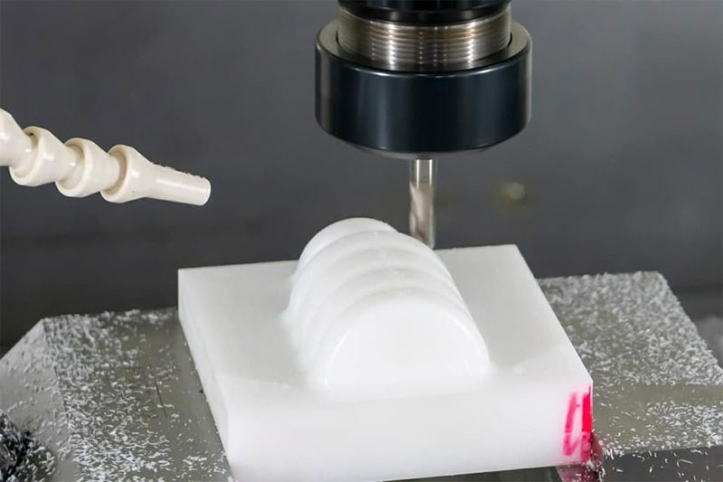
5. Typical Milling Operations
- Profiling: Creating keyways, grooves, or profiles along the rod. Ensure the rod is adequately supported at both ends or use a tailstock to prevent deflection.
- Slotting: To produce radial slots or circumferential grooves, use a narrow cutter (e.g., 3 mm–5 mm) at slow feed rates (≈0.1 mm/tooth) and shallow DOC (≈0.5 mm). Multiple passes may be necessary to reach final depth.
- Facing and Squaring: If the rod end faces have been turned, light facing in a milling machine can refine flatness and square ends—use minimal DOC (≈0.2 mm) and moderate feed (≈0.2 mm/tooth).
PTFE Rods Drilling
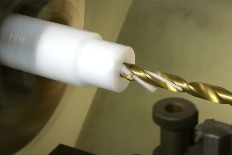
Drilling holes in PTFE rods is common for applications like fluid ports, mounting features, or sensor passages. Achieving a clean, burr-free hole requires appropriate drill geometry, speeds, and pecking strategies.
1. Drill Bit Selection
- Standard Twist Drills: High-speed steel (HSS) bits with polished flutes are adequate. For better chip evacuation, consider parabolic-flute drills.
- Specialty PTFE Drills: A drill with a slight split point (135°) reduces thrust and centers more accurately, helping to start holes without wandering on soft surfaces.
- Diameter Considerations: For holes below 6 mm, a peck drilling approach is critical; larger diameters can be drilled in multiple increments.
2. Workholding
- Centering the Hole: Use a spotting drill (e.g., 60° tip) or center drill to create a small dimple, preventing the main drill from walking across the PTFE surface. Because PTFE is soft, a light touch—slow feed and low thrust—during spotting reduces tearing.
- Backing Material: Place a sacrificial backing (e.g., wood or soft aluminum) under the rod to support the drill exit, preventing tear-out and ensuring a clean back surface.
- Vise with Soft Jaws: In a drill press or milling machine, clamp the rod in soft jaws or between padded jaws. Over-tightening can cause deformation; apply only enough force to prevent rotation.
3. Cutting Parameters
- Spindle Speed: High speeds—1,500–2,500 RPM for drill diameters up to 10 mm—help produce clean holes. Slower speeds risk producing long chips that stick in the flutes.
- Feed Rate: A feed of 0.05–0.12 mm/rev prevents chip packing. Too low a feed causes rubbing and melting; too high risks pulling the probe through the hole.
- Peck Drilling Strategy: Retract the drill every 2–3 mm of penetration to break chips and clear flutes. Pecking reduces heat and prevents chips from smearing on the hole walls.
4. Hole Quality and Finishing
- Reaming: To achieve precise hole diameters and excellent surface finish (<1 µm Ra), a light finishing reamer may be used. Run the reamer at moderate speed (≈1,000 RPM) with very light feed (≈0.02 mm/rev).
- Chamfering: After drilling, chamfer the hole entrance and exit with a small countersink (82°–90°) to remove any burrs, ensuring smooth edges.
- Deburring: PTFE chips can cling to hole edges. Using a brush or compressed air can clear the debris. If necessary, a deburring tool with a small scraper can lightly remove residual burrs, taking care not to gouge the material.
Best Practices and Common Challenges
- Dimensional Stability: After machining, PTFE parts may exhibit slight creep over time. Whenever dimensional tolerances are tight (±0.05 mm or better), consider machining allowances and finalizing critical dimensions after an equilibration period (24–48 hours) at room temperature.
- Tool Wear Monitoring: Although PTFE is soft, tool edges can dull from rubbing rather than cutting. Inspect cutting edges regularly—dull edges increase friction, heat, and smearing.
- Workpiece Cleaning: PTFE chips and dust can cling electrostatically. Use a soft brush or compressed air to clear chips; avoid cloth wiping with solvents, as solvent residues can interfere with the final application.
- Avoiding Heat Build-Up: Constant monitoring of tool–workpiece interface is essential. If the PTFE surface shows glossiness or burn marks, reduce speed, increase feed, or shorten contact time.
- Fixturing for Complex Features: For features such as multi-axis profiles or angled holes, custom fixtures or 4- to 5-axis CNC setups may be necessary. Ensure robust clamping and consider using vacuum fixtures where practical.
- Surface Finish Goals: For sliding or sealing surfaces, a low surface roughness—typically Ra 0.4 µm–0.8 µm—is desired. Achieve this by using sharp tools, shallow finishing cuts, and minimal vibration.