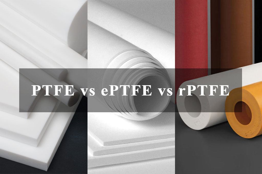
Beyond standard PTFE, two significant variants – expanded PTFE (ePTFE) and reinforced PTFE (rPTFE), have been developed to address specific application requirements.
While all three materials share a common chemical backbone of –(CF₂–CF₂)ₙ–, their microstructures, mechanical properties, and performance characteristics differ substantially.
This article explores the fundamental differences between PTFE, ePTFE, and rPTFE, examining their manufacturing processes, physical properties, advantages, limitations, and typical applications.
What Is PTFE?
Chemical Structure and Properties
Regular PTFE is a linear polymer composed of repeating tetrafluoroethylene monomers (CF₂–CF₂). Each carbon atom in the polymer chain is fully fluorinated, leading to the following hallmark properties:
- Chemical Inertness: PTFE is virtually unaffected by acids, bases, solvents, and most reagents due to the strong carbon–fluorine bonds.
- Wide Temperature Range: Continuous service up to ~260 °C (500 °F) and down to cryogenic temperatures (–200 °C or –328 °F).
- Low Coefficient of Friction: Static and dynamic coefficients of friction as low as 0.05–0.10, making PTFE an outstanding bearing and sliding material.
- Dielectric Properties: Excellent electrical insulating performance, with a dielectric constant of ~2.1 at 1 MHz and dielectric strength exceeding 60 kV/mm.
- Non-Adhesive Surface: PTFE’s surface energy is extremely low (~18 mN/m), leading to non-stick behavior in cookware and industrial applications.
Manufacturing Process
PTFE is produced by the radical polymerization of tetrafluoroethylene gas under high pressure (typically 100–200 bar) at controlled temperatures. The resulting polymer is a fine white powder (virgin PTFE) that can be shaped via one of two primary processes:
- Ram Extrusion: PTFE powder is mixed with a lubricant (e.g., aliphatic hydrocarbon), pre-formed into billets, and then ram-extruded. The extrudate is sintered (heated above the crystalline melt point, ~327 °C) to remove lubricant and consolidate the polymer.
- Paste Extrusion (Molding): PTFE powder is mixed into a paste, compressed into molds, and then baked (sintered) to achieve the final part geometry.
Because PTFE does not flow like typical thermoplastics (it’s not a true melt-processable polymer), machining and molding require specialized techniques. After sintering, PTFE exhibits high crystallinity (50–70%), contributing to its density (~2.2 g/cm³) and mechanical strength. However, virgin PTFE typically has relatively low tensile strength (10–30 MPa) and elongation at break (200–300%), which can limit its use in load-bearing applications without further modification.
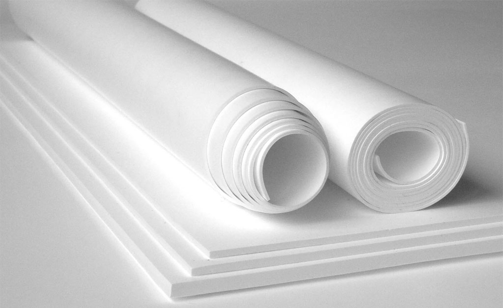
What Is ePTFE (Expanded PTFE)?
Manufacturing and Microstructure
Expanded PTFE (ePTFE) is created by subjecting consolidated PTFE to a biaxial stretching process at elevated temperatures below its crystalline melt point. The general steps include:
- Paste or Ram Extrusion: Similar to standard PTFE, a billet or rod of PTFE is initially formed.
- Pre-Heated Stretching: The pre-form is heated to ~300–320 °C (slightly below the melting point) to soften the polymer without melting it completely.
- Biaxial Expansion: Mechanical stretching in both longitudinal and transverse directions at a controlled rate induces fibrillation, creating a microstructure of nodes (crystallites) interconnected by fibrils (thin polymer strands). Typical expansion ratios range from 10× to over 100× in surface area.
- Stabilization: After expansion, the material is annealed at ~340 °C to lock in the microstructure and relieve internal stresses.
This controlled expansion transforms solid PTFE into a porous, microporous membrane with pore sizes typically in the range of 0.1 to 3 µm, depending on the stretch ratio and process parameters. The resulting ePTFE has a density as low as 0.5 g/cm³ or lower, compared to ~2.2 g/cm³ for virgin PTFE.
Key Characteristics
- Porosity and Breathability: ePTFE’s network of interconnected pores allows for gas permeability (e.g., water vapor transmission) while remaining liquid-impermeable (hydrophobic). This makes ePTFE ideal for breathable membranes.
- High Tensile Strength: The fibrillar node–fibrous network structure provides tensile strengths typically in the range of 30–50 MPa, with elongation at break from 100 % to 300 %, depending on the expansion ratio.
- Low Coefficient of Friction: Although slightly higher than virgin PTFE, ePTFE retains low friction (≈0.10–0.15).
- Thermal Stability: Similar to non-expanded PTFE, ePTFE performs from cryogenic temperatures up to ~260 °C.
- Chemical Resistance: Retains the chemical inertness of PTFE.
Typical Applications
- Filtration Membranes: ePTFE filters particulates down to sub-micron levels, with oil–water separation, venting, and vent membrane applications (e.g., electronic enclosures, fuel systems).
- Gaskets and Seals: Compression-molded or skived gaskets derived from ePTFE deliver lower creep and cold flow, suiting dynamic sealing applications (e.g., pharmaceutical, food processing, chemical industries).
- Medical Implants: Expanded PTFE (e.g., Gore-Tex®) is used in vascular grafts, surgical meshes, and soft tissue implants, owing to its biocompatibility and microporous architecture that encourages tissue in-growth.
- Protective Clothing: ePTFE laminates (e.g., Gore-Tex® fabrics) provide waterproof yet breathable textiles in outdoor gear.
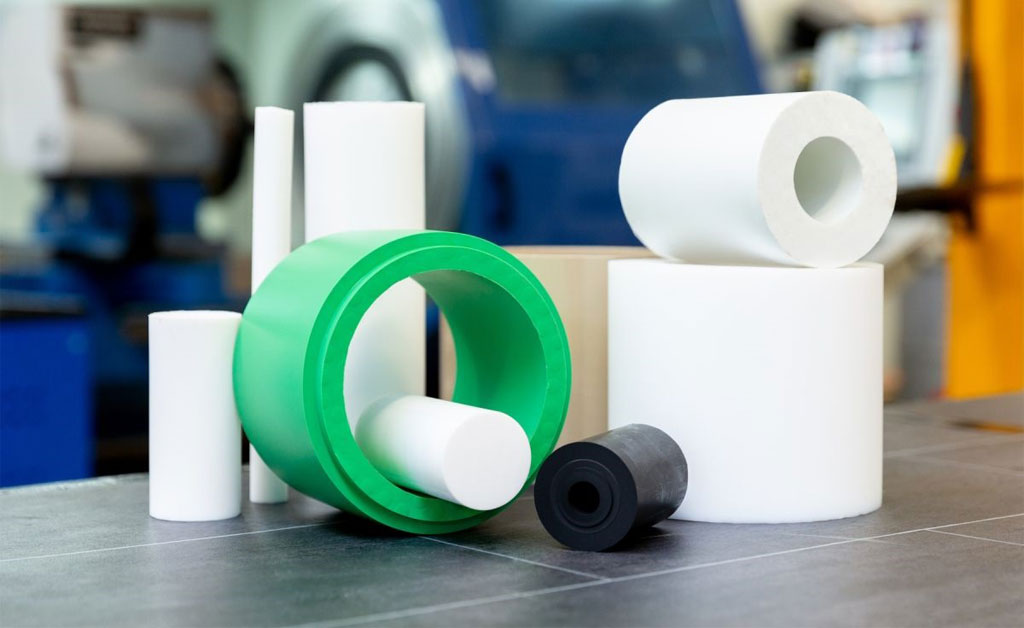
What Is rPTFE (Reinforced PTFE)?
Concept and Reinforcement Strategies
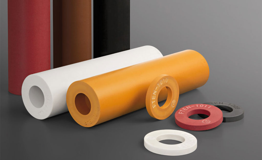
Reinforced PTFE (rPTFE) refers to PTFE that has been mechanically or chemically modified by incorporating fillers (fibers, powders, or whiskers) or by mechanical compounding to enhance mechanical strength, reduce creep, and improve wear resistance. Key reinforcement strategies include:
- Fibrous Fillers: Glass fibers, carbon fibers, or aramid (Kevlar®) fibers can be blended with PTFE powder. Typical fiber loadings range from 1 % to 15 % by weight. These fibrous reinforcements improve tensile strength (up to 40–70 MPa) and reduce elongation (<100 %) compared to virgin PTFE.
- Powdered Fillers: Inorganic fillers such as bronze, graphite, molybdenum disulfide (MoS₂), silica, or stainless-steel powders (typically 10 %–40 % by weight) are incorporated. These fillers enhance:
- Wear Resistance: Graphite and MoS₂ lower the coefficient of friction further and improve dry sliding wear characteristics.
- Thermal Conductivity: Metal powders (e.g., bronze, copper) increase heat dissipation.
- Dimensional Stability: Fillers reduce cold flow (creep) under load, which is a well-known drawback of virgin PTFE.
- Fillers and Fibers Combined: Some specialized rPTFE formulations combine both fibers and powders to balance multiple properties, such as graphite + glass fiber or bronze + Kevlar®.
Manufacturing Process
The general steps for producing rPTFE include:
- Mixing and Blending: PTFE powder is dry-blended with the chosen fillers (fibers and/or powders) in a high-intensity blender to achieve a uniform dispersion. Occasionally, a lubricant (e.g., aliphatic hydrocarbon) is added to facilitate mixing and later processing.
- Paste Extrusion or Ram Extrusion: The blended powder mixture is then consolidated by paste extrusion or ram extrusion into billets or finished shapes. The extrusion process aligns fibrous reinforcements along the flow direction, which enhances anisotropic properties.
- Sintering: The extruded part is sintered at ~330–360 °C to remove lubricant (if used) and to coalesce the PTFE matrix around the reinforcement network.
- Post-Processing: Machining (turning, milling, drilling) is often required to achieve final dimensions, as PTFE cannot be injection-molded in conventional ways.
The resulting rPTFE parts exhibit enhanced stiffness, reduced creep, improved wear resistance, and sometimes tailored thermal and electrical properties depending on the filler type.
Key Characteristics
- Mechanical Strength and Stiffness: Depending on filler type and content, tensile strength can exceed 50 MPa, and modulus can increase by 2× to 5× over virgin PTFE. Compressive and flexural strengths are also significantly improved.
- Reduced Creep and Deformation: Load-carrying capacity under static or cyclic stress is greatly enhanced. Standard PTFE can exhibit up to 20 % to 30 % cold flow under moderate loads; rPTFE can reduce creep to below 1 % in similar conditions.
- Enhanced Wear Resistance: Graphite-filled and MoS₂-filled PTFE exhibit coefficients of friction as low as 0.05–0.08 and greatly extended service life in sliding applications (e.g., bearings, slide plates).
- Thermal Conductivity: Metal-filled grades (bronze, copper) can exhibit thermal conductivities up to 5 W/(m·K) versus 0.25 W/(m·K) for virgin PTFE, facilitating heat dissipation in applications like heat exchanger seals.
- Electrical Properties: Some rPTFE grades loaded with conductive fillers (e.g., carbon or metal powders) can be electrically conductive or semi-conductive, enabling applications in EMI shielding or static dissipation.
However, the inclusion of fillers often compromises the very-low surface energy and extreme chemical inertness of virgin PTFE. Metallurgical fillers, for instance, can introduce chemical susceptibility (e.g., bronze can corrode in acid environments). Moreover, higher filler loadings may increase density (up to ~3.0–3.5 g/cm³) and limit flexibility.
Comparing PTFE, ePTFE, and rPTFE
| Property | PTFE (Virgin) | ePTFE (Expanded) | rPTFE (Reinforced) |
|---|---|---|---|
| Microstructure | Dense, semi-crystalline | Microporous fibril-node network | Dense with dispersed fillers |
| Density (g/cm³) | ~2.2 | 0.3–1.0 (depending on expansion) | 2.2–3.5 (depending on filler content) |
| Tensile Strength (MPa) | 10–30 | 30–50 | 30–70+ |
| Elongation at Break (%) | 200–300 | 100–300 (varies with expansion) | 50–200 (varies with filler type/amount) |
| Coefficient of Friction | 0.05–0.10 | 0.10–0.15 | 0.05–0.20 (depending on filler) |
| Creep Resistance | Low (20–30 % under load) | Moderate (reduced vs. PTFE) | High (creep <1 %) |
| Thermal Conductivity (W/m·K) | ~0.25 | ~0.10 (due to porosity) | Up to ~5.0 (metal-filled grades) |
| Temperature Range (°C) | –200 to +260 | –200 to +260 | –200 to +260 (some fillers limit highs) |
| Chemical Resistance | Excellent | Excellent | Variable (metal fillers may corrode) |
| Electrical Insulation | Excellent (ε_r ≈2.1) | Good (porosity may limit dielectric) | Variable (conductive fillers may lower) |
| Typical Applications | Seals, gaskets, bearings | Filters, medical implants, membranes | Bearings, wear strips, high-load seals |
Key Differences Summarized
- Structure and Morphology
- PTFE: Uniform, nonporous material.
- ePTFE: Porous, networked fibril-node structure formed by expansion.
- rPTFE: Solid PTFE matrix with discrete filler particles or fibers integrated.
- Mechanical Performance
- PTFE: Moderate tensile strength, high elongation, low stiffness, high creep.
- ePTFE: Improved tensile strength relative to PTFE, lower stiffness than reinforced grades, moderate creep.
- rPTFE: Highest tensile strength and modulus, lowest creep, tailored stiffness.
- Friction and Wear
- PTFE: Lowest friction but wears more quickly under load.
- ePTFE: Slightly higher friction due to porous surface but improved wear compared to PTFE.
- rPTFE: Wear performance depends on filler; graphite- or MoS₂-filled grades exhibit extremely low friction and exceptional wear life.
- Porosity and Permeability
- PTFE: Non-porous—impermeable to gases and liquids.
- ePTFE: Highly porous—gas-permeable, liquid-impermeable (hydrophobic).
- rPTFE: Non-porous (unless intentionally modified), impermeable.
- Thermal and Electrical Properties
- PTFE & ePTFE: Very low thermal conductivity, excellent dielectric properties.
- rPTFE: Thermal and electrical properties can be engineered via filler choice; can be conductive or highly thermally conductive.
- Chemical Resistance
- PTFE & ePTFE: Outstanding chemical inertness—resistant to nearly all chemicals (except molten alkali metals and fluorine at high temperatures).
- rPTFE: Retains much of PTFE’s chemical resistance, but filler materials may introduce vulnerability (e.g., oxidation or corrosion of metal fillers).
Applications and Selection Considerations
When to Use PTFE
- Static Seals and Gaskets: Applications where chemical compatibility is paramount and loads are moderate, such as in chemical processing valves, flange seals, and static chemical-resistant seals.
- Low-Friction Bearings: Dry-running bearings or sliding components where minimal friction is desired without high loads.
- Electrical Insulation: Cable jacketing, wire insulation, and high-frequency circuit boards where dielectric losses must be minimal.
- Food and Pharmaceutical: PTFE’s inertness and compliance with FDA, USP Class VI, and other certifications make it suitable for contact with food, medicine, and high-purity applications.
When to Use ePTFE
- Filtration and Membrane Separation: ePTFE’s microporous structure enables sub-micron filtration of particulates, bacteria, and aerosols. Typical uses include liquid filtration, venting membranes (e.g., breather vents for enclosures), and water–oil separation.
- Medical Implants: Vascular grafts, sutures, and surgical meshes exploit ePTFE’s biocompatibility, tissue in-growth, and flexibility.
- Seals Requiring Elastic Recovery: ePTFE gaskets can recover more effectively after compression, reducing the need for high bolt loads in flange assemblies.
- Breathable Fabrics: Laminates of ePTFE with stretchable textiles (e.g., jackets, boots) offer waterproof yet breathable performance for outdoor clothing.
When to Use rPTFE
- High-Load Bearings and Bushings: Applications such as pump bearings, valve seats, and slide rails in which load capacity and wear resistance are critical. Graphite-filled rPTFE bushings are common in steel mill equipment.
- Dynamic Seals Under Pressure: rPTFE’s dimensional stability and creep resistance ensure longer service life in reciprocating or rotating seals (e.g., O-rings, U-cup packings) in hydraulic and pneumatic systems.
- Thermal Management: Metal-filled rPTFE gaskets and spacers in heat exchangers or electrical devices where heat dissipation is required.
- EMI/RFI Shielding and Conductive Components: Carbon- or metal-filled rPTFE can be used in electronic enclosures to provide electromagnetic shielding or in anti-static flooring solutions.
Pingback: Is PTFE Tubing Safe? 5 Data-Backed Truths for Industrial & Medical Use in 2025 - Yozonetech Co., Ltd.